Dipole Antenna Ends Arc Ceramic

20 Ceramic Dogbone Insulators For Dipole Antenna Inverted V Ham Radio Shortwave Dipole Antenna Antenna Ham Radio

Slinktenna 80m 6m Helical Dipole Hf Ham Radio Antenna Etsy Ham Radio Antenna Ham Radio Radio Antenna

Diy Easy 2m Dipole Antenna Dipole Antenna Ham Radio Antenna Fm Antenna Diy

Broadband Butterfly Terminated Dipole Antenna Bbtd Bow Tie Configuration With 2 Supports Ham Radio Antenna Antennas Ham Radio

Center Dipole Insulator Inverted V Stealth Antenna Diy Antenna Dipole Antenna Insulation

Antenna Insulators

10 current flow in dipole antenna 17 fig.
Dipole antenna ends arc ceramic.

Arc Flash Hazard Flashover With Images Electricity Arc Flash Engineering

4 Ceramic Dogbone Insulators For Dipole Inverted V Antenna Ham Radio Shortwave Ebay
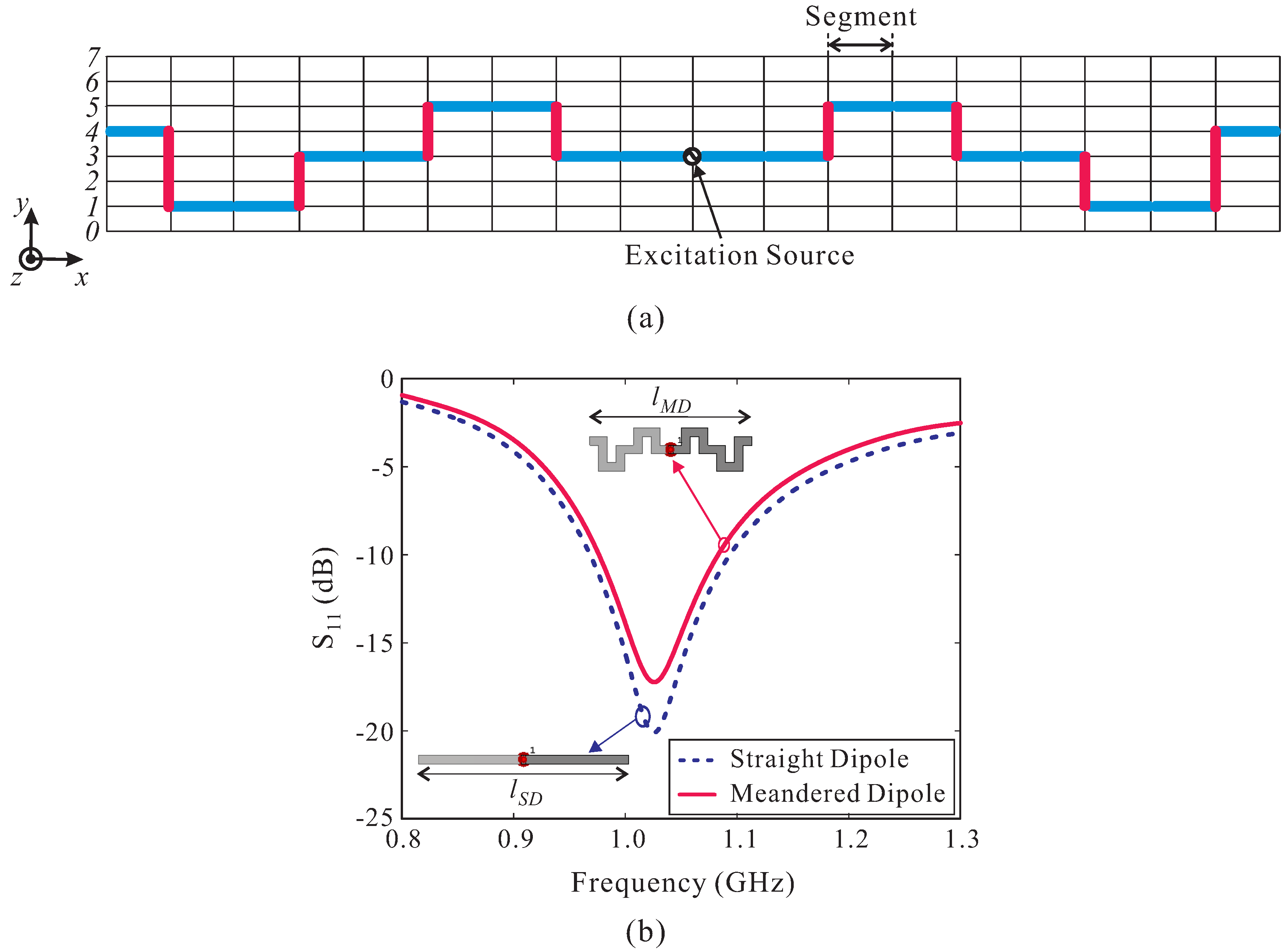
Sensors Free Full Text A Low Profile High Gain And Wideband Log Periodic Meandered Dipole Array Antenna With A Cascaded Multi Section Artificial Magnetic Conductor Structure Html

Pin On Ham Radio

Field Expedient Antenna Systems Amrron

20 Dx Vertical Antenna Ocf No Radials Ldg Rt 100 Atu For 160 6m Ham Radio Ham Radio Antenna Dipole Antenna

Alpha Delta Dx Ultra Shortwave Dipole Antenna Am Broadcast 30 Mhz Ebay

Dimensions For Building A Homebrew Sirio Gain Master Using Rg 58 2 5 Mm2 Insulated Stranded Copper Wire And Westflex Home Brewing Ham Radio Ham Radio Antenna

Eham Net

Wire Antennas For Ham Radio Radiolyubitel Radio Elektronika

Attic Multi Band Dipole Ham Radio Antenna Ham Radio Diy Tv Antenna

Here039s A Picture Of The Radio Shack Attic Antennas Ham Radio Within Measurements 2592 X 1944 Ham Radio Ham Radio Antenna Dipole Antenna

Dimensions For Building A Homebrew Sirio Gain Master Using Rg 58 2 5 Mm2 Insulated Stranded Copper Wire And Westflex In 2020 Home Brewing Ham Radio Ham Radio Antenna

1830nvis An Ideal Antenna For Military Mars Apartment Dweller And Restricted Communities No Antenna Tuner Needed Ham Radio Radio Radio Antenna

Antenna Hf Dipole 5 Mhz 60m Band Radio 1000w Antena Rotary Ssb 13 Metres Lenght Ebay

Ocf Dipole Whoa Holy Cow

Homebrew Buddipole Free Download As Pdf File Pdf Text File Txt Or Read Online For Free Antenna For Tx Rx Radio Band Home Brewing Antenna

Pin On Antenne
Https Encrypted Tbn0 Gstatic Com Images Q Tbn 3aand9gctf6fxkv Be0qzwt44qzdf Dd9jvxoguz3tbjimysq0d5fuq6n4 Usqp Cau
W4neq 130 Foot Doublet Open Wire Line

Dipole Antenna For Sale In Stock Ebay

N233n On Display At Victoria Conference Dipole Antenna Ham Radio Diagram

Schematic Of 16 1 Balun By Mel K6kbe Ham Radio Antenna Ham Radio Antennas

Pin On Amateur Radio
Source : pinterest.com
